# VXLAN# ensp&virtualbox 设置1. 导入 CE 镜像
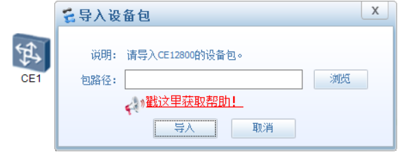
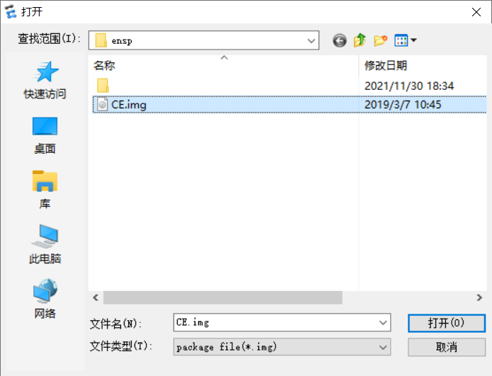
拖一台 CE12800,启动设备,系统会让自动选择镜像,选择 CE 镜像,正确的镜像为 1.3G 的
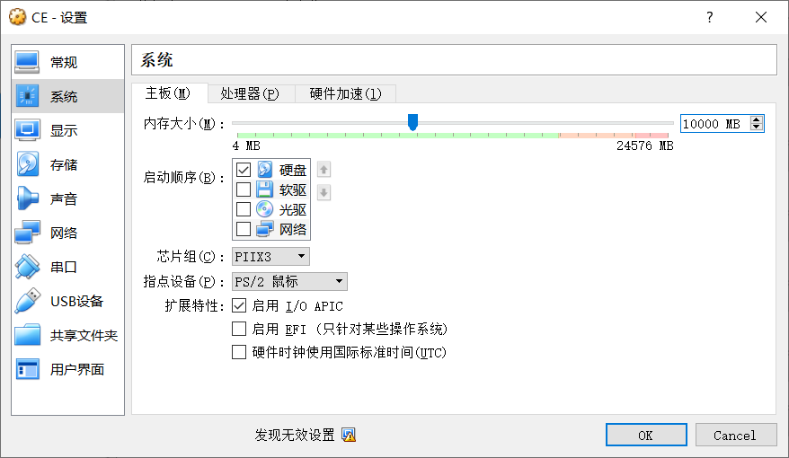
导入后 virtualbox 中会显示
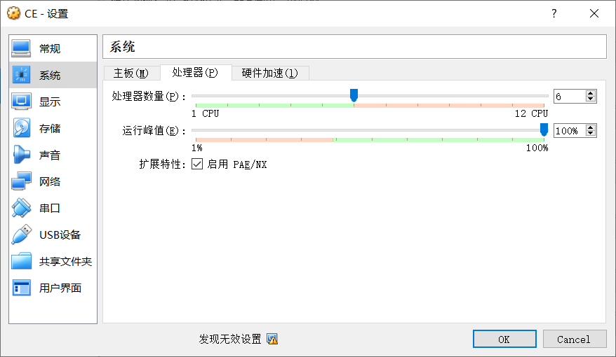
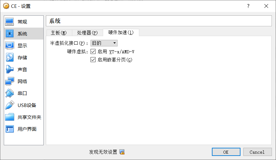
更改 CE 设置,设置内存,每台 CE12800 大概需要 1G 内存
# VXLANVXLAN 是由 IETF 定义的 NVO3 (Network Virtualization over Layer 3) 标准技术之一,采用 L2 over L4 ( MAC-in-UDP) 的报文封装模式,将二层报文用三层协议进行封装,可实现二层网络在三层范围内进行扩展,同时满足数据中心大二层虚拟迁移和多租户的需求。
Vxlan 是一种无控制平面,利用底层 IP 网络实现二层通信的隧道技术。
GRE 也是无控制平面,不需要使用协议维护隧道状态。比如 LDP 是 LSP 的控制平面。
底层的 IP 网络称为 Underlay 网络,Vxlan 则称为 Overlayer 网络。
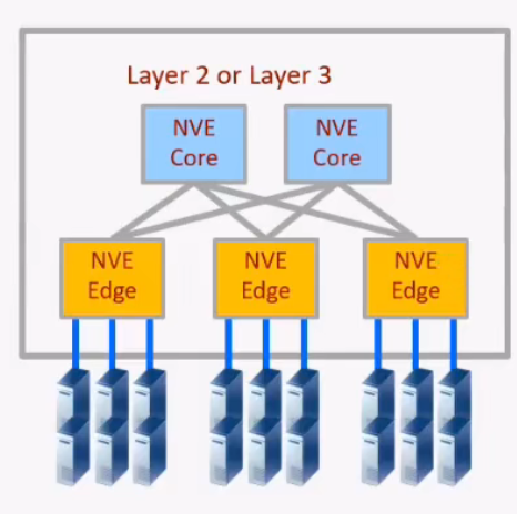
# 名词解释# NVO3 & NVENVO3 (Network Virtualization Over Layer 3), 基于三层 IP overlay 网络构建虚拟网络技术统称为 NVO3。运行 NVO3 的设备叫做 NVE (NetworkVirtualization Edge) ,它位于 overlay 网络的边界,实现二、三层的虚拟化功能。NVE 是执行 VXLAN 封装和接封装的设备
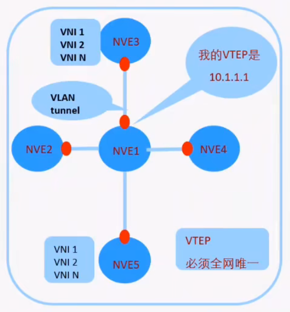
# VTEPVXLAN 网络中的 NVE 以 VTEP 进行标识 ,VTEP (VXLAN Tunnel Endpoint,VXLAN 隧道端点)
VTEP 即标识设备,也标识 VXLAN 隧道,两个 VTEP 地址之间唯一的确定一条 VXLAN 隧道。所以 VTEP 的地址要求全网可达
# VNIVNI - VXLAN 网络标识符
VNI 是一种类似于 VLANID 的用户标示,一个 VNl 代表了一个租户 ,属于不同 VNI 的虚拟机之间不能直接进行二层通信。VXLAN 报文封装时,给 VNI 分配了足够的空间使其可以支持海量租户的隔离。
应用场景
虚拟机在同一网段需要互访的情景,在没有 VXLAN 是,只能在同一个物理机上。使用 VXLAN,可以去除网络限制,使资源分配
2 层 VPN:封装的对象是帧,VXLAN,TRILL,L2TP,PPTP,VPLS
3 层 VPN:封装的对象是包,IPSEC,GRE,DSVPN,MPLS VPN
ipsec vpn 隧道模式,3 层 vpn
ipsec vpn 传输模式,只封装 IP 之上的内容
应用层 VPN:SSL VPN
MPLS VPN:三层
VPLS:二层
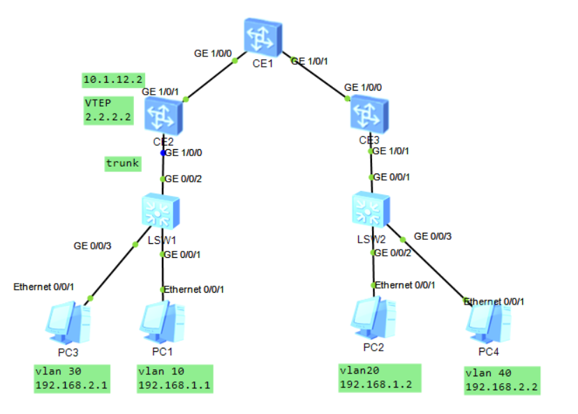
# 实验 1: 同子网互访1 2 3 4 5 6 7 8 9 10 11 12 13 14 15 16 17 18 19 LSW1 & LSW2 trunk - access CE1 & CE2 & CE3 1.underlay 配置物理接口&环回口地址 配置路由协议 2.VXLAN业务接入配置 配置BD域:BD域用于在NVE上本地区分不同的大二层网络,本地有效,没有全局意义,每一个BD域只能关联一个vni,在一台NVE上不同BD域需要关联不同VNI bridge-domain 10 VXLAN vni 10 将vlanid和BD域关联,BD域又和vni关联 int g1/0/0.10 mode l2 encapsulation dot1q vid 10 bridge-domain 10 创建VXLAN隧道 int nve 1 source 2.2.2.2 vin 10 head-end peer-list 3.3.3.3
1 2 3 4 5 6 7 8 9 10 11 12 13 14 15 16 17 18 19 20 21 22 23 24 25 26 27 28 29 30 31 32 33 34 35 36 37 38 39 40 41 42 43 44 45 46 47 48 49 50 51 52 53 54 55 56 57 58 59 60 61 62 63 64 65 66 67 68 69 70 71 72 73 74 75 76 77 78 79 80 81 82 83 84 85 86 LSW1 vlan batch 10 20 30 40 # interface GigabitEthernet0/0/1 port link-type access port default vlan 10 # interface GigabitEthernet0/0/2 port link-type trunk port trunk allow-pass vlan 2 to 4094 # interface GigabitEthernet0/0/3 port link-type access port default vlan 30 CE2 bridge-domain 10 vxlan vni 10 # bridge-domain 20 vxlan vni 20 # rip 1 version 2 network 2.0.0.0 network 10.0.0.0 # interface GE1/0/0 undo shutdown # interface GE1/0/0.10 mode l2 encapsulation dot1q vid 10 bridge-domain 10 # interface GE1/0/0.30 mode l2 encapsulation dot1q vid 30 bridge-domain 20 # interface GE1/0/1 undo portswitch undo shutdown ip address 10.1.12.2 255.255.255.0 # interface LoopBack0 ip address 2.2.2.2 255.255.255.255 # interface Nve1 source 2.2.2.2 vni 10 head-end peer-list 3.3.3.3 vni 20 head-end peer-list 3.3.3.3 CE3 bridge-domain 20 vxlan vni 10 # bridge-domain 30 vxlan vni 20 # rip 1 version 2 network 3.0.0.0 network 10.0.0.0 # interface GE1/0/0 undo portswitch undo shutdown ip address 10.1.13.3 255.255.255.0 # interface GE1/0/1 undo shutdown # interface GE1/0/1.20 mode l2 encapsulation dot1q vid 20 bridge-domain 20 # interface GE1/0/1.40 mode l2 encapsulation dot1q vid 40 bridge-domain 30 # interface LoopBack0 ip address 3.3.3.3 255.255.255.255 # interface Nve1 source 3.3.3.3 vni 10 head-end peer-list 2.2.2.2 vni 20 head-end peer-list 2.2.2.2
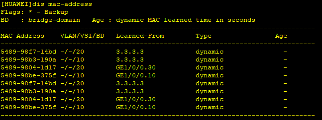
数据帧在 CE2 通过子接口,MAC,BD 上形成 MAC 地址表
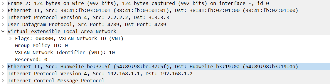
MAC-IN-UDP 通过封装 UDP 实现按照流的负载分担,Dport 4789
在 VXLAN 中,不关心主机所在 VXLAN,只要在同一网段即可实现
既可以实现网络虚拟化,将网络虚拟为两个不同的虚拟网络,租户之间网络隔离
此时逻辑拓扑变为虚拟交换机连接同一租户的不同设备
在公有云场景,为了适应虚拟机迁移的场景,使用 SDN 动态下发配置
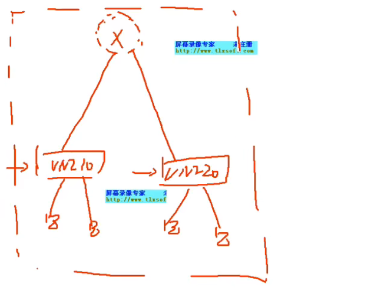
VXLAN 头端复制
将 VXLAN 报文复制多份发给每一个当前 vni 中的 peer list
vxlan 网络对 BUM 报文的转发行为默认是头端复制 broadcast-unknown-Multicast
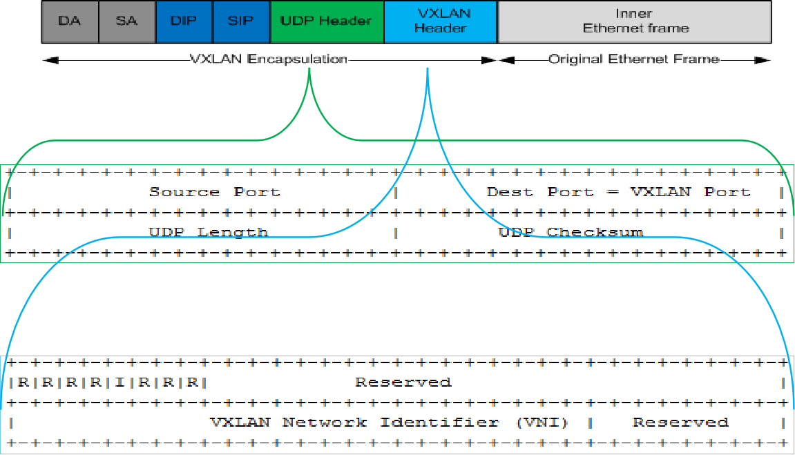
VXLAN I flag: 必须置为 1,标识 VNI 字段有效。
UDP Dest Port: VXLAN 保留 UDP 目的端口号,默认为 4789
UDP Source Port: 根据数据流 HASH 动态生成。
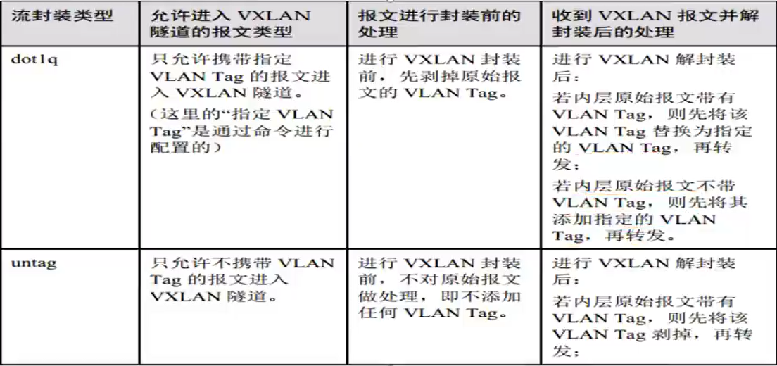
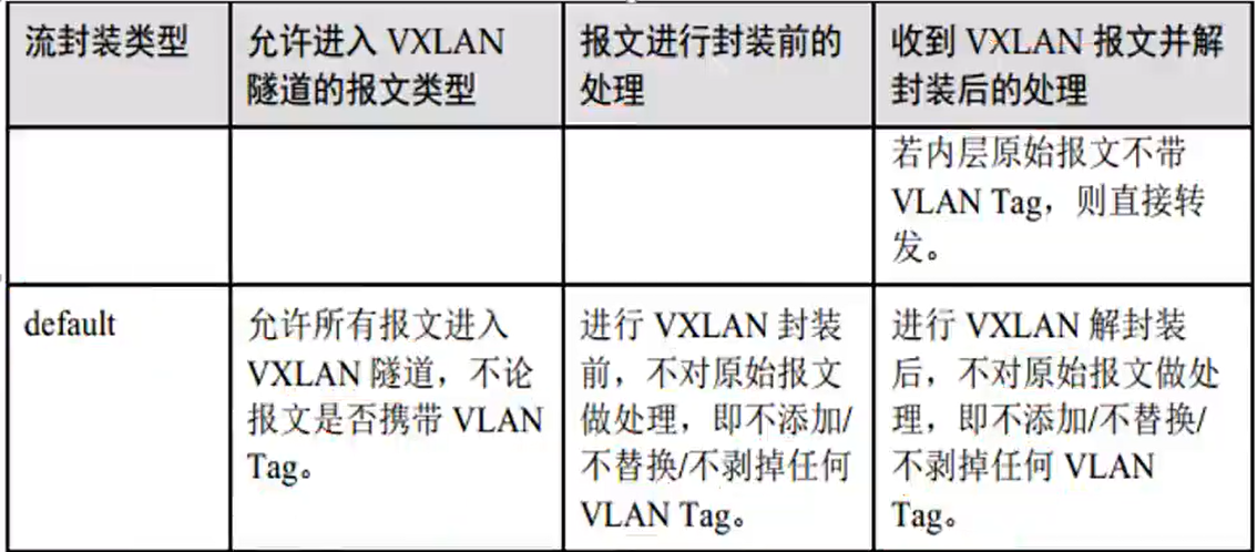
不同流封装类型的接口对报文的处理方式
一个物理接口下如果存在 default 接口,那么不能存在其他类型的接口
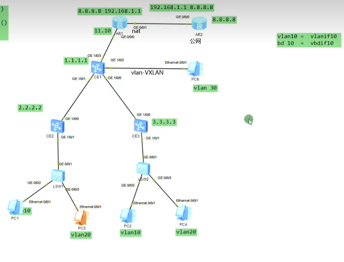
# 实验二:跨子网互通(集中式网关)1 2 3 4 5 6 7 8 9 10 11 12 13 14 15 16 17 18 19 20 21 22 23 24 25 26 27 28 29 30 31 32 33 34 35 36 37 38 39 40 41 42 43 44 45 46 47 48 49 50 51 52 53 54 55 56 57 58 CE1作为网关 bridge-domain 10 bridge-domain 20 int vbdif 10 ip add 192.168.1.254 24 int vbdif 20 ip add 192.168.2.254 24 CE2 - CE1 建立VXLAN int nve 1 vni 10 head peer 1.1.1.1 vni 20 head peer 1.1.1.1 CE3 - CE1 建立VXLAN int nve 1 vni 10 head peer 1.1.1.1 vni 20 head peer 1.1.1.1 int nv1 vni 10 head peer 2.2.2.2 3.3.3.3 vni 20 head peer 2.2.2.2 3.3.3.3 主机网关设置vdbif接口地址 对于多租户在网关上使用ip vpn-instance 实现 ip vpn-instance A route-dist 1:1 int vbdif 10 ip binding vpn-instance 10 ip add int vbdif 20 ip binding vpn-instance 10 ip add 对于每一个租户分配一个VPN-instance 对于普通的vlan网络,设置接口类型,vlanif接口,即可实现vlan与VXLAN互通 对于需要访问外网的场景 将VPN-instance中的路由泄露到public中,在VPN-instance中添加了一条静态路由 ip route-static vpn-instance A 0.0.0.0 0 10.1.11.10 public 注意回包路由 1.将租户路由引回私网中 ip route-static 192.168.1.1 24 10.1.11.1 2.将public泄露到vpn中,public中会有一下一跳为VPN-instance的路由,迭代到出接口vbdif ip route-static 192.168.1.0 24 vpn-instance A 192.168.1.1 要求 1.对于同一租户,同子网和跨子网互通 2.vlan和VXLAN互通 3.VXLAN中租户和公网互通 4.CE1旁挂防火墙,实现路由隔离,nat在fw上,租户互通通过fw
网络虚拟化,对于租户来说,只消耗 vni 和直连路由
1 2 3 4 5 6 7 8 9 10 11 12 13 14 15 16 17 18 19 20 21 22 23 24 25 26 27 28 29 30 31 32 33 34 35 36 37 38 39 40 41 42 43 44 45 46 47 48 49 50 51 52 53 54 55 56 57 58 59 60 61 62 63 64 65 66 67 68 69 70 71 72 73 74 75 76 77 78 79 80 81 82 83 84 85 86 87 88 89 90 91 92 93 94 95 96 97 98 99 100 101 102 103 104 105 106 107 108 109 110 111 112 113 114 115 116 117 118 CE1 vlan batch 10 20 30 # ip vpn-instance A ipv4-family route-distinguisher 1:1 # bridge-domain 10 vxlan vni 10 # bridge-domain 20 vxlan vni 20 # rip 1 version 2 network 1.0.0.0 network 10.0.0.0 # interface Vbdif10 ip binding vpn-instance A ip address 192.168.1.254 255.255.255.0 # interface Vbdif20 ip binding vpn-instance A ip address 192.168.2.254 255.255.255.0 # interface Vlanif30 ip address 192.168.3.254 255.255.255.0 # interface GE1/0/0 undo portswitch undo shutdown ip address 10.1.12.1 255.255.255.0 # interface GE1/0/1 undo portswitch undo shutdown ip address 10.1.13.1 255.255.255.0 # interface GE1/0/2 undo portswitch undo shutdown ip address 10.1.11.1 255.255.255.0 # interface GE1/0/3 undo shutdown port default vlan 30 # interface LoopBack0 ip address 1.1.1.1 255.255.255.255 # interface Nve1 source 1.1.1.1 vni 10 head-end peer-list 2.2.2.2 vni 10 head-end peer-list 3.3.3.3 vni 20 head-end peer-list 2.2.2.2 vni 20 head-end peer-list 3.3.3.3 # ip route-static 192.168.1.0 255.255.255.0 vpn-instance A 192.168.1.1 ip route-static 192.168.2.0 255.255.255.0 vpn-instance A 192.168.2.1 ip route-static vpn-instance A 0.0.0.0 0.0.0.0 10.1.11.2 public CE2 vlan batch 10 20 # bridge-domain 10 vxlan vni 10 # bridge-domain 20 vxlan vni 20 # rip 1 version 2 network 2.0.0.0 network 10.0.0.0 # interface GE1/0/0 undo portswitch undo shutdown ip address 10.1.12.2 255.255.255.0 # interface GE1/0/1 undo shutdown # interface GE1/0/1.10 mode l2 encapsulation dot1q vid 10 bridge-domain 10 # interface GE1/0/1.20 mode l2 encapsulation dot1q vid 20 bridge-domain 20 # interface LoopBack0 ip address 2.2.2.2 255.255.255.255 # interface Nve1 source 2.2.2.2 vni 10 head-end peer-list 1.1.1.1 vni 10 head-end peer-list 3.3.3.3 vni 20 head-end peer-list 1.1.1.1 vni 20 head-end peer-list 3.3.3.3 AR1 acl number 2000 rule 5 permit source 192.168.1.0 0.0.0.255 rule 10 permit source 192.168.2.0 0.0.0.255 # interface GigabitEthernet0/0/0 ip address 10.1.11.2 255.255.255.0 # interface GigabitEthernet0/0/1 ip address 10.1.21.1 255.255.255.0 nat outbound 2000 # ip route-static 0.0.0.0 0.0.0.0 10.1.21.2 ip route-static 192.168.1.0 255.255.255.0 10.1.11.1 ip route-static 192.168.2.0 255.255.255.0 10.1.11.1
两个 VTEP 可以确定一条 VXLAN 隧道,VTEP 间的这条 VXLAN 隧道将被两个 NVE 间的所有 VNI 所共用。
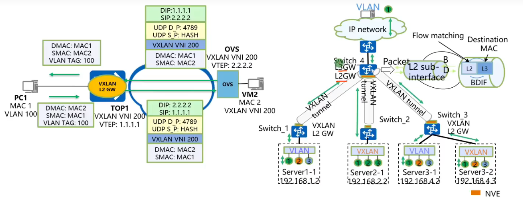
VXLAN 二层网关:允许租户接入 VxLAN 网络,实现相同 VxLAN 内部流量互访。
VxLAN L3 Gateway: 实现不同 VxLAN 直接互访,或者 VxLAN 与非 VxLAN 网络互访。
L2-Subif: 用于用户接入,子接口上可以配置一层 tag 接入或者不配置 tag 接入;
BD (Bridge-Domain): 标识一个二层广播域,BD 和 VNI 1:1 映射。所有广播域功能基于 BD 支持,如 MAC 学习、二层查表、广播复制等;
NVE (Network Virtualization Edge): 主要用于本地 VTEP 地址管理,VXLAN 隧道管理,头端复制列表管理;
VXLAN 隧道: VXLAN 隧道用于 VXLAN 报文的转发,用本地 VTEP 地址 + 远端 VTEP 地址标识﹔
BDIF:BD 域的三层路由接口,用于二层流量进入三层进行路由转发;
bridge-domain 20
L2 binding vlan 10 // 全局关联 vlan 端口到 BD 域中
VLAN 绑定 BD 后,该 BD 不支持创建对应的 VBDIF 接口。同时不支持创建该 VLAN 对应的 VLANIF 接口。
VLAN 绑定 BD 功能和 ARP 广播报文抑制功能互斥,配置 VLAN 为 VXLAN 业务接入点后,不建议再使能 ARP 广播报文抑制功能
ARP 广播抑制:抑制后续的 ARP 广播报文,由于首包之后 CE 上已经有了 arp 请求的主机的位置,只需要单播请求即可。arp 广播请求变 arp 单播请求
第一次虚拟化:利用隧道技术将边缘设备互连透传二层报文;整网抽象理解成一台端口数目扩展的超大 LAN switch。
第二次虚拟化利用 VNI 将这台超大的交换机虚拟出多个二层的广播域,和 VLAN 本质是一样的,VNI 类比 VLANID. 并通过定义 VXLAN header 中的 VNI 字段,将子网范围由 4K 扩展至 16M。
vxlan 主要优点
基于 IP 的 overlay, 仅需要边界设备间 IP 可达。
隧道间水平分割、IP overlay TTL 避免环路。 网络层收到的 VXLAN 报文只能发给用户侧
数据流量基于 IP 路由 SPF 及 ECMP 快速转发。
网络变化实时侦听全网拓扑毫秒收敛
Overlay+VNI 构建虚拟网络,支持多达 16M 的虚拟网络。
物理设备、vSwitch 均能够部署。CE1800V 软件交换机也能做 VXLAN
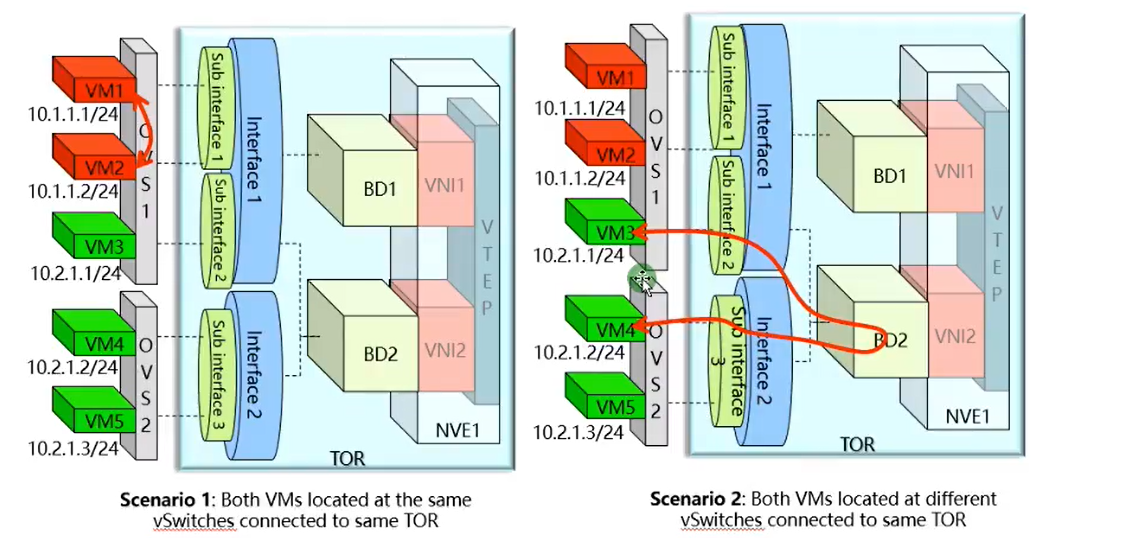
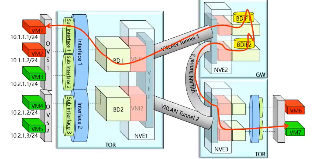
VXLAN 同子网互访模型
1. 同一 OVS 之间
2. 不同 OVS 之间
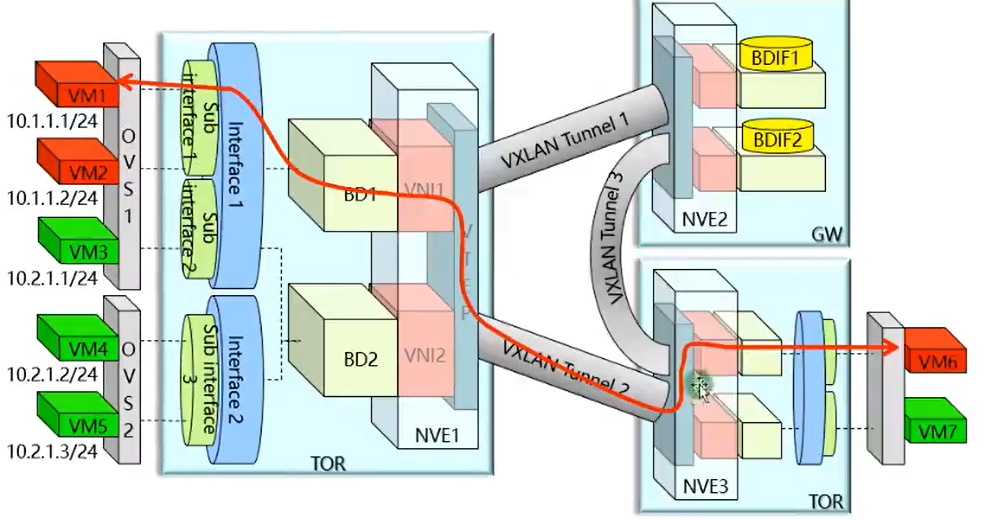
3. 不同 tor 之间
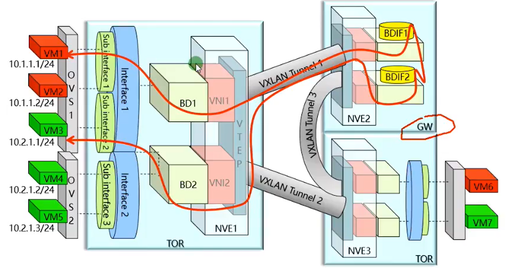
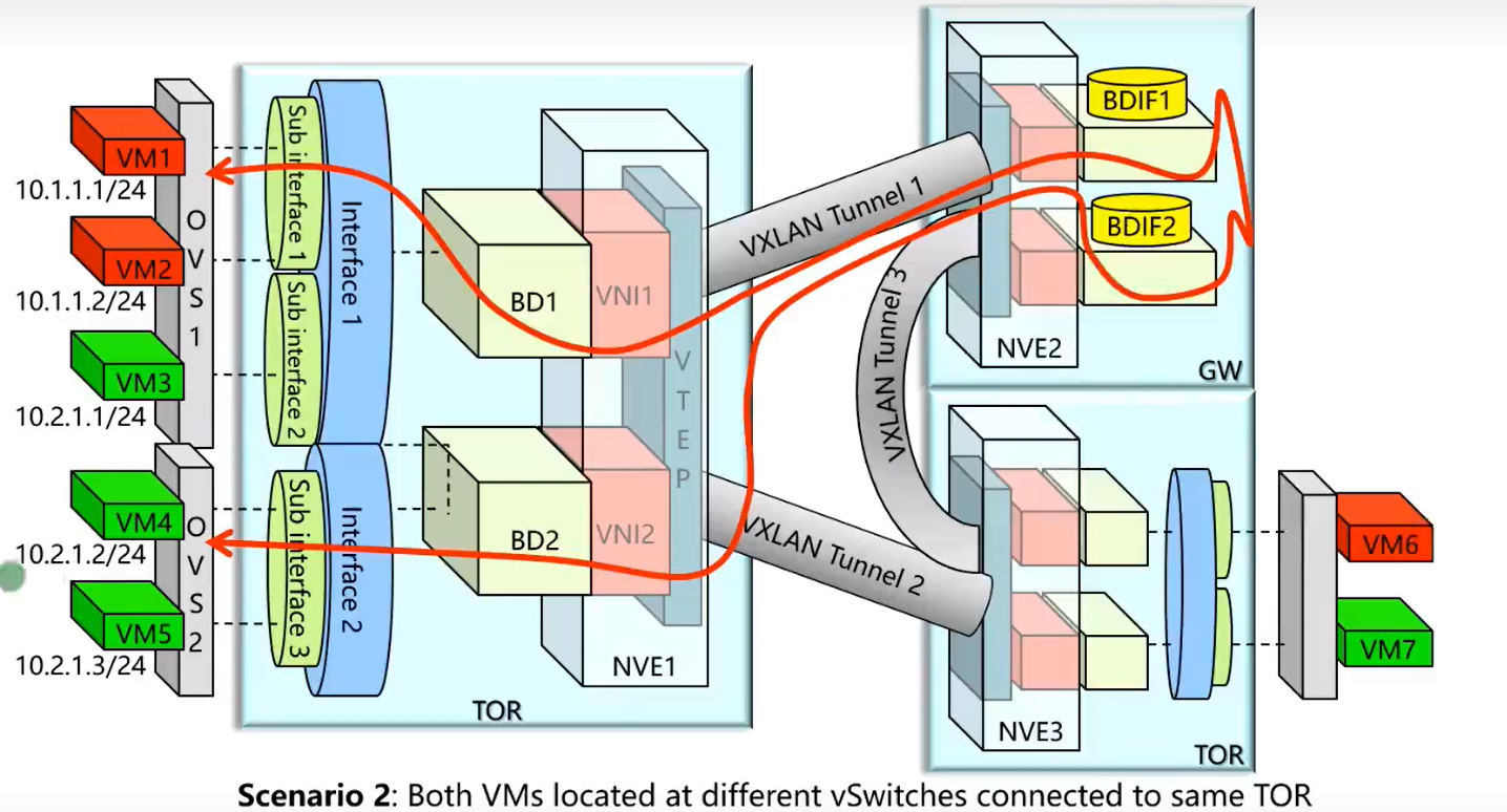
VXLAN 不同子网护网
集中式网关
1. 流量迂回
2. 网关 arp 表项过多可能成为网络瓶颈
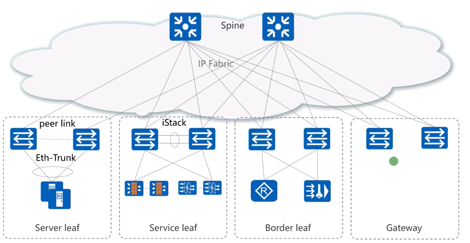
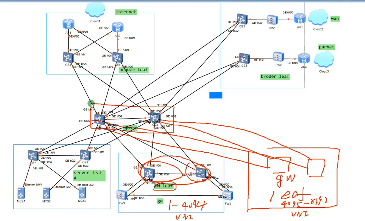
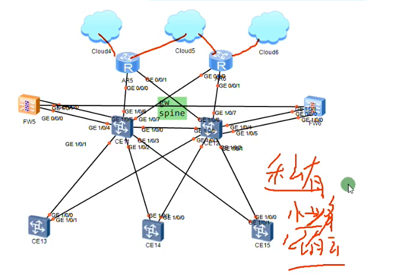
VXLAN 基于 spine-leaf 组网架构
胖树
spine 和网关分离部署,解决集中式网关容量问题
spine 和网关融合部署
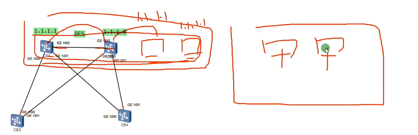
集中式网关场景下网关双活
华为最多支持四台做多活,但只提高转发效率,不提高表项
表项通过 DFS 同步
需要通过双活组做网关扩容
多活网关需要 VTEP 一样
CE 模拟器基于包做负载分担
集中式网关特点
1. 流量存在迂回现象
2. 网关需要维护主机的 mac 地址信息和 arp 信息,对设备表项容量要求高,容易遇到瓶颈
3. 网关容易存在单点故障
4. 跨子网的流量都由网关来完成,流量有明显控制点,网关维护用户路由信息,MAC 地址,ARP 表项,VXLAN 隧道路由
leaf 只需要维护 MAC 地址信息和 VXLAN 隧道的路由信息,无需维护用户的路由信息
第一个和第二三个问题可以采用分布式网关解决
第三个问题可以使用双活网关解决
如果非要用集中式网关
1. 第一个问题无法解决
2. 第二个问题采用多组网关解决容量问题
3. 第三个问题采用多活网关
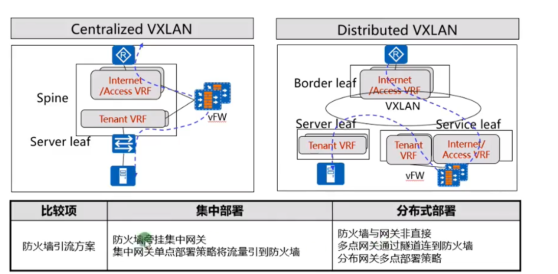
集中式网关有网关和 spine 融合组网 适用业务稳定,规模稳定的私有云
网关和 spine 分离组网 适用于业务变更频繁业务规模可以弹性伸缩的时候,中大型公有云和私有云
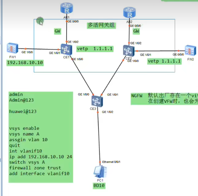
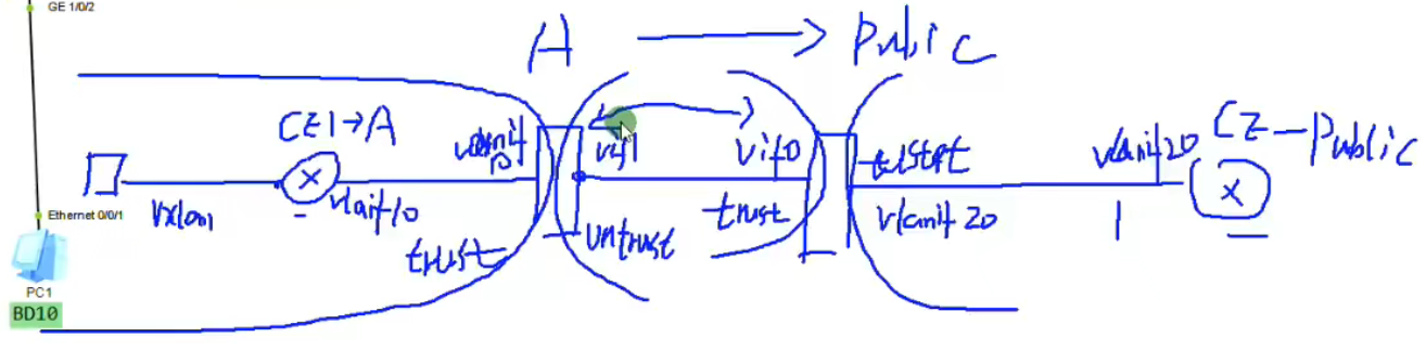
# 集中式双活网关过墙
1 2 3 4 5 6 7 8 9 10 11 12 13 14 15 16 17 18 19 20 21 22 23 24 25 26 27 28 29 30 31 32 33 34 35 36 37 38 39 40 41 42 43 44 45 46 47 48 49 50 51 52 53 54 55 56 57 58 59 60 61 62 63 64 65 66 67 68 69 70 71 72 73 74 75 76 77 78 79 80 81 82 83 84 85 86 87 88 89 90 91 92 93 94 95 96 97 网关上创建互联vlan 一个vlan绑定到用户的VPN-instance中,用于和用户的vfw实现三层互连 一个vlan绑定到public中,和root防火墙实现三层互联,此链路所有租户共享 fw上创建互联vlan 一个vlan关联到租户的虚墙,实现和租户在gw上的VPN-instance对接 一个vlan关联root防火墙和gw的public对接 gw vlan 10 des vpn A vlan 20 des public int g1/0/1 p l t p t a v a int vlanif 10 ip add 192.168.10.1 24 ip bing vpn A int vlan 20 ip add 192.168.20.1 24 ip route vpn A 0.0.0.0 0 192.168.10.10 ip rou 0.0.0.0 0 192.168.30.1 ip rou 202.1.1.0 24 192.168.20.20 fw vlan 10 20 int g1/0/0 portswitch p l t p t a v a vsys enable vsys name A assign vlan 10 int vlanif 10 ip add 192.168.10.10 24 service pin p switch vsys A firewall zone trust add interface vlanif 10 //华为NGFW默认出厂存在一个virtual-if0,它属于root的一个逻辑接口,用于和虚拟fw的virtual-if接口实现通信 在创建vfw时,也会为vfw自动创建一个virtual-if接口,接口号设备自行分配 Firewall zone untrust add inter vitural-if 1 firewall zone trust add inter vit 0 int vlan 20 ip add 192.168.20.20 24 service pin p firewall zon un add int vlan 20 switch vsys A ip route-static 192.168.1.0 24 192.168.10.1 security-po ru name test trust->untrust sourece 192.168.1.0 ac pe ip route 0.0.0.0 0 public security-policy def ac per ip route 0.0.0.0 0 192.168.20.1 nat add A section 202.1.1.1 202.1.1.10 vsys name A assign global 202.1.1.1 202.1.1.10 free switch vsys A nat add A sec 202.1.1.1 202.1.1.3 nat-policy ru name A source-zon t de un source 192.168.1.0 24 ac so add A ip rou 202.1.1.0 28 vpn A R1 ip rou 202.1.1.0 24 192.168.30.1
1 2 3 4 5 6 7 8 9 10 11 12 13 14 15 16 17 18 19 20 21 22 23 24 25 26 27 28 29 30 31 32 33 34 35 36 37 38 39 40 41 42 43 44 45 46 47 48 49 50 51 52 53 54 55 56 57 58 59 60 61 62 63 64 65 66 67 68 69 70 //1.网关双活 [CE1]dis cu ip vpn-instance A ipv4-family route-distinguisher 100:1 # bridge-domain 10 vxlan vni 10 # interface Vbdif10 ip binding vpn-instance A ip address 192.168.1.254 255.255.255.0 mac-address 5489-9825-6da0 # interface GE1/0/0 undo portswitch undo shutdown ip address 10.1.13.1 255.255.255.0 # interface GE1/0/1 undo shutdown # interface GE1/0/2 undo shutdown # interface LoopBack0 ip address 1.1.1.1 255.255.255.255 # interface Nve1 source 1.1.1.1 vni 10 head-end peer-list 3.3.3.3 # rip 1 version 2 network 1.0.0.0 network 10.0.0.0 [CE3]dis cu bridge-domain 10 vxlan vni 1 # interface GE1/0/0 undo portswitch undo shutdown ip address 10.1.13.3 255.255.255.0 # interface GE1/0/1 undo portswitch undo shutdown ip address 10.1.23.3 255.255.255.0 # interface GE1/0/2 undo shutdown # interface GE1/0/2.10 mode l2 encapsulation untag bridge-domain 10 # interface LoopBack0 ip address 3.3.3.3 255.255.255.255 # interface Nve1 source 3.3.3.3 vni 10 head-end peer-list 1.1.1.1 # rip 1 version 2 network 3.0.0.0 network 10.0.0.0
1 2 3 4 5 6 7 8 9 10 11 12 13 14 15 16 17 18 19 20 21 22 23 24 25 26 27 28 29 30 31 32 33 34 35 36 37 38 39 40 41 42 43 44 45 46 47 48 49 50 51 52 53 54 55 56 57 58 59 60 61 62 63 64 65 66 67 68 69 70 71 72 73 74 75 76 77 78 79 80 81 82 83 84 85 86 87 88 89 90 91 92 93 94 95 96 97 98 99 100 101 102 103 104 105 106 107 108 109 110 111 112 113 114 115 116 117 118 119 120 121 122 123 124 125 126 127 128 129 130 131 132 133 134 135 136 137 138 139 140 141 142 143 144 145 146 147 //网关双活过墙 [CE1]di cu vlan batch 10 20 30 # ip vpn-instance A ipv4-family route-distinguisher 100:1 # vlan 10 description VPN-instance A # bridge-domain 10 vxlan vni 10 # interface Vbdif10 ip binding vpn-instance A ip address 192.168.1.254 255.255.255.0 mac-address 5489-9825-6da0 # interface Vlanif10 ip binding vpn-instance A ip address 192.168.10.1 255.255.255.0 # interface Vlanif20 description public ip address 192.168.20.1 255.255.255.0 # interface GE1/0/0 undo portswitch undo shutdown ip address 10.1.13.1 255.255.255.0 # interface GE1/0/1 undo shutdown port link-type trunk port trunk allow-pass vlan 2 to 4094 # interface GE1/0/2 undo portswitch undo shutdown ip address 192.168.30.1 255.255.255.0 # interface LoopBack0 ip address 1.1.1.1 255.255.255.255 # interface Nve1 source 1.1.1.1 vni 10 head-end peer-list 3.3.3.3 # rip 1 version 2 network 1.0.0.0 network 10.0.0.0 # ip route-static 0.0.0.0 0.0.0.0 192.168.30.30 ip route-static 202.1.1.0 255.255.255.0 192.168.20.20 ip route-static vpn-instance A 0.0.0.0 0.0.0.0 192.168.10.10 [USG6000V1]dis cu vlan batch 10 20 30 # vsys enable # vsys name A 1 assign vlan 10 assign global-ip 201.1.1.1 202.1.1.10 free # interface Vlanif10 ip binding vpn-instance A ip address 192.168.10.10 255.255.255.0 service-manage ping permit # interface Vlanif20 ip address 192.168.20.20 255.255.255.0 service-manage ping permit # interface GigabitEthernet1/0/0 portswitch undo shutdown port link-type trunk port trunk allow-pass vlan 2 to 4094 # firewall zone trust set priority 85 add interface GigabitEthernet0/0/0 add interface Virtual-if0 # firewall zone untrust set priority 5 add interface Vlanif20 # ip route-static 0.0.0.0 0.0.0.0 192.168.20.1 ip route-static 202.1.1.0 255.255.255.240 vpn-instance A # security-policy default action permit rule name test # switch vsys A # interface Vlanif10 ip binding vpn-instance A ip address 192.168.10.10 255.255.255.0 service-manage ping permit # firewall zone trust set priority 85 add interface Vlanif10 # firewall zone untrust set priority 5 add interface Virtual-if1 # nat address-group A 0 mode pat section 0 202.1.1.1 202.1.1.3 # security-policy rule name test source-zone trust destination-zone untrust source-address 192.168.1.0 mask 255.255.255.0 action permit # nat-policy rule name A source-zone trust destination-zone untrust source-address 192.168.1.0 mask 255.255.255.0 action source-nat address-group A # ip route-static 0.0.0.0 0.0.0.0 public ip route-static 192.168.1.0 255.255.255.0 192.168.10.1 [R1]dis cu [V200R003C00] interface GigabitEthernet0/0/0 ip address 192.168.30.30 255.255.255.0 # interface LoopBack0 ip address 8.8.8.8 255.255.255.255 # ip route-static 202.1.1.0 255.255.255.0 192.168.30.1
# EVPNEVPN 作为数据中心 VXLAN 技术的控制平面,转发平面还是采用 VXLAN 对数据进行封装
EVPN 支持集中式网关组网,也支持分布式网关组网
EVPN 在数据中心实现同子网互访和跨子网互访
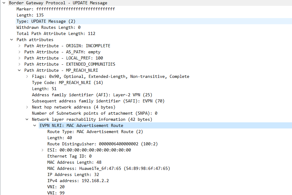
为了在数据中心支持 VXLAN。EVPN 在 BGP 协议的基础上新增了一种 NLRI,称为 EVPN NLRI
EVPN NLRI 定义了三种路由信息
1.type 2 路由称为 MAC/IP 路由,根据不同的作用,也称为 ARP 路由 / IRB 路由(IRB 集成的路由与桥接),用于
@数据中心支持 ARP 广播抑制
@动态虚拟机迁移
@虚拟机主机路由的发布,实现跨子网互访
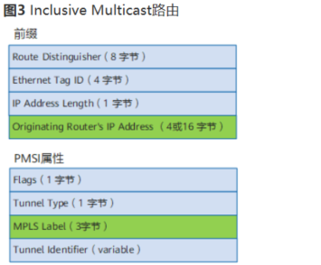
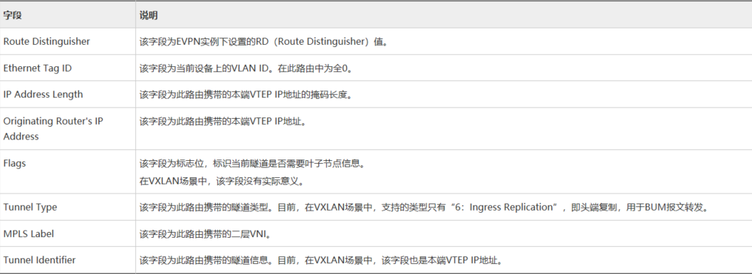
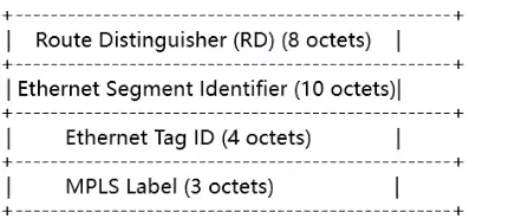
2.type 3 路由,称为集成组播路由,用于在 VTEP 之间动态建立 VXLAN 隧道,并动态实现头端复制列表的生成,用于支持 BUM 报文的转发
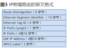
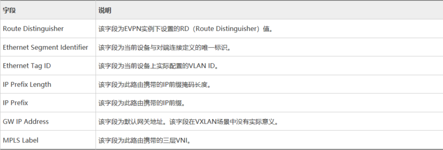
3.type 5 路由,称为前缀路由,常用于将数据中心外部路由引入到各租户的 VPN-instance 中,实现数据中心内部访问外部
另外标准的 EVPN 协议还定义了 type 1 的路由
type 1 路由 Ethernet AD Route (auto discovery)
双归场景下用于防环快速收敛,别名
type 4 路由,Ethernet Segment Route
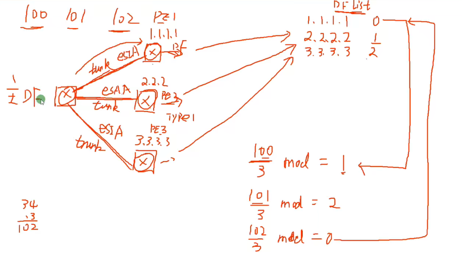
双归场景下用于实现 DF 的选举和执行负载分担的维护
1 2 3 4 5 6 7 8 9 10 11 12 13 14 15 16 17 18 19 20 21 22 23 24 25 26 27 28 29 30 31 32 33 34 35 36 37 38 39 40 41 42 43 44 45 46 47 48 49 50 51 52 53 54 55 56 57 58 59 60 61 62 63 64 65 66 67 68 69 70 //CE1-CE4之间建立EVPN邻居 CE1 evpn-overlay enable bgp 100 peer 2.2.2.2 as 100 peer 2.2.2.2 con l 0 peer 3.3.3.3 peer 4.4.4.4 l2vpn-fa evpn peer 2.2.2.2 enable peer 2.2.2.2 re peer 3.3.3.3 peer 4.4.4.4 //peer 2.2.2.2 ad arp //peer 3.3.3.3 ad arp //peer 4.4.4.4 ad arp undo p v CE2 evpn-overlay enable bgp 100 peer 1.1.1.1 as 100 peer 1.1.1.1 con l 0 l2vpn-fa evpn peer 1.1.1.1 en //peer 1.1.1.1 ad arp dis bgp evpn peer CE2-CE3-CE4 BD 10 vx 10 evpn router- 100:1 vpn-t 100:1 b int g1/0/1.10 bd 10 enca 10 //EVPN实例中本地的每个BD域都可以看成是一个独立的EVPN实例,一个二层的广播域 int Nve1 source 2.2.2.2 vni 10 head peer pro bgp //type3 dis bgp evpn rout in 0:32:2.2.2.2 CE4 int vbdif 10 ip add 192.168.1.254 24 没有反射器的场景需要在所有节点建立全互联EVPN CE2-CE3 ip vpn- A router 100:1 vpn 100:1 both evpn vxlan vni 100 //三层VNI int vbdif 10 ip bin vpn A arp dist enable arp collect host enable ip addr
Type3 路由 ——Inclusive Multicast 路由
还会携带 ERT,不在 EVPN 中,在 BGP 中,用于设置感兴趣路由
1. 对方收到 type3 路由后,比较 RT 是否匹配,如果匹配则接收该 type3 的路由
2. 提取 type3 中 org router ip (VTEP 地址) ,如果该地址路由可达,则创建 VXLAN 隧道
3. 提取 PMSI 属性中二层 VNI 值,看是否和本端 EVPN 实例中的相同,如果相同则将 PSMI 中携带的 VTEP 地址添加到 VXLAN 隧道的头端复制列表中
如果希望在 EVPN 邻居之间传递 type2 的路由 (ARP 路由 / IRB 路由)
peer 1.1.1.1 advertise arp 传递 ARP 路由 / MAC 路由
peer 1.1.1.1 advertise irb 传递 IRB 类型的路由
默认只传 type3
MAC route 实现 VM 之间二层互访,需要在 EVPN 邻居之间传递 MAC route
MAC route 特征
携带 RD+MAC + 二层 VNI
为了支持 ARP 广播抑制和虚拟机热迁移,需要在 EVPN 邻居之间传递 ARP 类型的路由
传递 IRB peer 1.1.1.1 ad irb
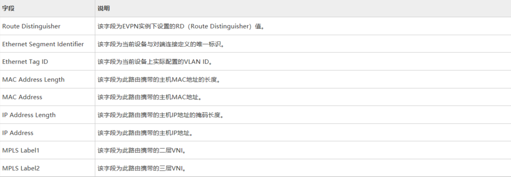
Type2 路由 ——MAC/IP 路由
arp 路由的特征:携带 RD+MAC+IP + 二层 VNI
irb 类型的特征:携带 RD+MAC+IP + 二层 VNI + 三层 VNI,irb 类型的路由也具备 arp 类型路由的功能
什么时候发送 ARP 类型的路由,集中式网关部署时发送 ARP 类型的路由即可
什么时候发送 IRB 类型的路由,分布式网关一定要发送 IRB 类型的路由
当邻居之间发布 arp 路由命令后,设备会将用户侧学到主机的 IP+MAC 信息通过 arp 类型的路由发送给 evpn 邻居
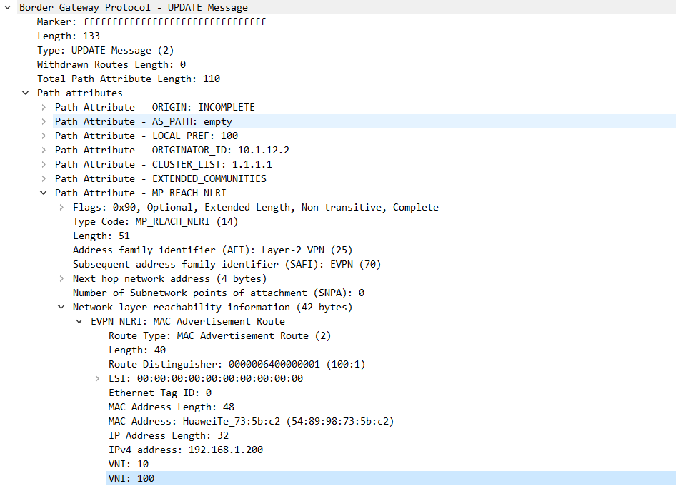
1 2 3 4 5 6 7 8 9 10 11 12 13 14 15 16 17 18 type 2路由在VXLAN控制平面中的作用包括: 主机MAC地址通告 要实现同子网主机的二层互访,两端VTEP需要相互学习主机MAC。作为BGP EVPN对等体的VTEP之间通过交换MAC/IP路由,可以相互通告已经获取到的主机MAC。其中,MAC Address Length和MAC Address字段为主机MAC地址。 主机ARP通告 MAC/IP路由可以同时携带主机MAC地址+主机IP地址,因此该路由可以用来在VTEP之间传递主机ARP表项,实现主机ARP通告。其中,MAC Address和MAC Address Length字段为主机MAC地址,IP Address和IP Address Length字段为主机IP地址。此时的MAC/IP路由也称为ARP类型路由。主机ARP通告主要用于以下两种场景: 1.ARP广播抑制。当三层网关学习到其子网下的主机ARP时,生成主机信息(包含主机IP地址、主机MAC地址、二层VNI、网关VTEP IP地址),然后通过传递ARP类型路由将主机信息同步到二层网关上。这样当二层网关再收到ARP请求时,先查找是否存在目的IP地址对应的主机信息,如果存在,则直接将ARP请求报文中的广播MAC地址替换为目的单播MAC地址,实现广播变单播,达到ARP广播抑制的目的。 2.分布式网关场景下的虚拟机迁移。当一台虚拟机从当前网关迁移到另一个网关下之后,新网关学习到该虚拟机的ARP(一般通过虚拟机发送免费ARP实现),并生成主机信息(包含主机IP地址、主机MAC地址、二层VNI、网关VTEP IP地址),然后通过传递ARP类型路由将主机信息发送给虚拟机的原网关。原网关收到后,感知到虚拟机的位置发生变化,触发ARP探测,当探测不到原位置的虚拟机时,撤销原位置虚拟机的ARP和主机路由。
1 2 3 4 5 6 7 8 9 10 11 12 13 14 15 16 17 18 19 20 21 22 23 24 25 26 27 28 29 30 31 32 33 34 35 36 37 38 39 40 41 42 43 44 45 46 47 48 49 50 51 52 53 54 55 56 57 58 59 60 61 62 63 64 65 66 67 68 69 70 71 72 73 74 75 76 77 78 79 80 81 82 83 84 85 86 87 88 89 90 91 92 93 94 95 96 97 [CE1]dis cu evpn-overlay enable # rip 1 version 2 network 10.0.0.0 network 1.0.0.0 # interface GE1/0/0 undo portswitch undo shutdown ip address 10.1.12.1 255.255.255.0 # interface GE1/0/1 undo portswitch undo shutdown ip address 10.1.13.1 255.255.255.0 # interface GE1/0/2 undo portswitch undo shutdown ip address 10.1.14.1 255.255.255.0 # interface LoopBack0 ip address 1.1.1.1 255.255.255.255 # bgp 100 peer 2.2.2.2 as-number 100 peer 2.2.2.2 connect-interface LoopBack0 peer 3.3.3.3 as-number 100 peer 3.3.3.3 connect-interface LoopBack0 peer 4.4.4.4 as-number 100 peer 4.4.4.4 connect-interface LoopBack0 # ipv4-family unicast peer 2.2.2.2 enable peer 3.3.3.3 enable peer 4.4.4.4 enable # l2vpn-family evpn undo policy vpn-target peer 2.2.2.2 enable peer 2.2.2.2 advertise irb peer 2.2.2.2 reflect-client peer 3.3.3.3 enable peer 3.3.3.3 advertise irb peer 3.3.3.3 reflect-client peer 4.4.4.4 enable peer 4.4.4.4 advertise irb peer 4.4.4.4 reflect-client [CE2]dis cu evpn-overlay enable # bridge-domain 10 vxlan vni 10 evpn route-distinguisher 100:1 vpn-target 100:1 export-extcommunity vpn-target 100:1 import-extcommunity # rip 1 version 2 network 10.0.0.0 network 2.0.0.0 # interface GE1/0/0 undo shutdown # interface GE1/0/0.10 mode l2 encapsulation dot1q vid 10 bridge-domain 10 # interface GE1/0/1 undo portswitch undo shutdown ip address 10.1.12.2 255.255.255.0 # interface LoopBack0 ip address 2.2.2.2 255.255.255.255 # interface Nve1 source 2.2.2.2 vni 10 head-end peer-list protocol bgp # bgp 100 peer 1.1.1.1 as-number 100 peer 1.1.1.1 connect-interface LoopBack0 # ipv4-family unicast peer 1.1.1.1 enable # l2vpn-family evpn policy vpn-target peer 1.1.1.1 enable peer 1.1.1.1 advertise irb
配置分布式网关并且通告 irb 类型路由后‘
# 分布式网关1 2 3 4 5 6 7 8 9 10 11 12 13 14 15 16 17 18 19 20 21 22 23 24 25 26 27 28 29 30 31 32 33 34 35 CE2-CE3 evpn en bgp 100 peer 3.3.3.3 as 100 peer 3.3.3.3 con l 0 l2vpn evpn peer 3.3.3.3 enable peer 3.3.3.3 ad irb bd 10 vxxlan 10 evpn route vpn-target 100:1 bbd 20 vpn 100:2 ip vpn-instance A route 100:1 vpn- 100:1 both vpn- 100:1 evpn vpn 100:2 evpn imp vxlan vni 99 int vbdif 10 ip bind vpn A ip add arp dis en arp coll host en int nv 1 source 2.2.2.2 vni 10 h p p bgp
二层 VNI 用于同子网互访
三层 VNI 用于实现跨子网互访
ARP 类型路由携带的有效信息有:主机 MAC 地址 + 主机 IP 地址 + 二层 VNI;IRB 类型路由携带的有效信息有:主机 MAC 地址 + 主机 IP 地址 + 二层 VNI + 三层 VNI。因此,IRB 类型路由包含着 ARP 类型路由,不仅可以用于主机 IP 路由通告,也能用于主机 ARP 通告。
主机 IP 路由通告
在分布式网关场景中,要实现跨子网主机的三层互访,两端 VTEP(作为三层网关)需要互相学习主机 IP 路由。作为 BGP EVPN 对等体的 VTEP 之间通过交换 MAC/IP 路由,可以相互通告已经获取到的主机 IP 路由。其中,IP Address Length 和 IP Address 字段为主机 IP 路由的目的地址,同时 MPLS Label2 字段必须携带三层 VNI。此时的 MAC/IP 路由也称为 IRB(Integrated Routing and Bridge)类型路由。
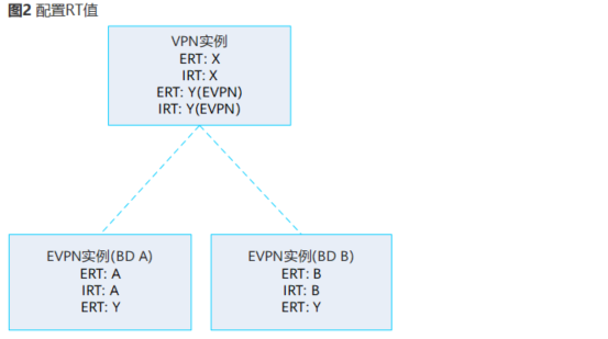
1.BD rt 匹配,如果匹配实现广播抑制虚拟机热迁移
2. 当 Eert 和本端 VPN-instance 中 Eirt 匹配时,会将其中携带的 IP 地址加入到 VPN-instance 路由表中,生成一条主机路由
export-rt evpn Eert
import-rt evpn Eirt
Leaf2 收到 Leaf1 发来的 BGP EVPN 路由后,同时进行如下处理:
检查该路由携带的 ERT,如果与本端 EVPN 实例的 IRT 相同,则接收该路由。EVPN 实例获取到 IRB 类型路由后,还能提取到其中包含的 ARP 类型路由,用于主机 ARP 通告。
检查该路由携带的 ERT,如果与本端 L3VPN 实例的 eIRT 相同,则接收该路由。然后,L3VPN 实例获取到该路由携带的 IRB 类型路由,从中提取 Host1 的主机 IP 地址、三层 VNI,在其路由表中保存 Host1 的主机 IP 路由,并根据路由的下一跳迭代出接口,最终迭代结果是指向 Leaf1 的 VXLAN 隧道,如图 6 所示。
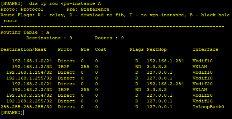
分布式网关只需要维护 rt 匹配的路由
dis ip rou vpn A
1 2 3 4 5 6 7 8 9 10 11 12 13 14 15 16 17 18 19 20 21 22 23 24 25 26 27 28 29 30 31 32 33 34 35 36 37 38 39 40 41 42 43 44 45 46 47 48 49 50 51 52 53 54 55 56 57 58 59 60 61 62 63 64 65 66 67 68 69 70 71 72 73 74 75 76 77 78 79 80 81 82 83 84 85 86 87 88 89 90 91 92 93 94 95 96 97 98 99 100 101 102 103 104 105 106 107 108 109 110 111 112 113 114 115 116 117 118 119 120 121 122 123 124 125 126 127 128 129 130 131 132 133 134 135 136 137 138 139 140 141 142 143 144 145 146 147 148 149 150 151 152 153 154 155 156 157 158 159 160 161 162 163 164 165 166 167 168 169 170 171 172 173 174 175 176 177 178 179 180 181 182 183 184 185 186 187 188 189 190 191 192 [CE3]di cu vlan batch 10 20 # evpn-overlay enable # ip vpn-instance A ipv4-family route-distinguisher 100:4 vpn-target 100:5 export-extcommunity vpn-target 100:22 export-extcommunity evpn vpn-target 100:5 import-extcommunity vpn-target 100:22 import-extcommunity evpn vxlan vni 99 # bridge-domain 10 vxlan vni 10 evpn route-distinguisher 100:1 vpn-target 100:11 export-extcommunity vpn-target 100:22 export-extcommunity vpn-target 100:11 import-extcommunity vpn-target 100:22 import-extcommunity # bridge-domain 20 vxlan vni 20 evpn route-distinguisher 100:2 vpn-target 100:3 export-extcommunity vpn-target 100:22 export-extcommunity vpn-target 100:100 export-extcommunity vpn-target 100:3 import-extcommunity vpn-target 100:22 import-extcommunity vpn-target 100:100 import-extcommunity # rip 1 version 2 network 3.0.0.0 network 10.0.0.0 # interface Vbdif10 ip binding vpn-instance A ip address 192.168.1.254 255.255.255.0 arp distribute-gateway enable arp collect host enable # interface Vbdif20 ip binding vpn-instance A ip address 192.168.2.254 255.255.255.0 arp distribute-gateway enable arp collect host enable # interface GE1/0/1 undo shutdown # interface GE1/0/1.10 mode l2 encapsulation dot1q vid 10 bridge-domain 10 # interface GE1/0/1.20 mode l2 encapsulation dot1q vid 20 bridge-domain 20 # interface GE1/0/6 undo portswitch undo shutdown ip address 10.1.13.3 255.255.255.0 # interface LoopBack0 ip address 3.3.3.3 255.255.255.255 # interface Nve1 source 3.3.3.3 vni 10 head-end peer-list protocol bgp vni 20 head-end peer-list protocol bgp # bgp 100 peer 2.2.2.2 as-number 100 peer 2.2.2.2 connect-interface LoopBack0 # ipv4-family unicast peer 2.2.2.2 enable # l2vpn-family evpn policy vpn-target peer 2.2.2.2 enable peer 2.2.2.2 advertise irb [CE1]dis cu evpn-overlay enable # rip 1 version 2 network 10.0.0.0 network 1.0.0.0 # interface GE1/0/3 undo portswitch undo shutdown ip address 10.1.13.1 255.255.255.0 # interface GE1/0/4 undo portswitch undo shutdown ip address 10.1.12.1 255.255.255.0 # interface LoopBack0 ip address 1.1.1.1 255.255.255.255 [CE2]dis cu vlan batch 10 20 # evpn-overlay enable # ip vpn-instance A ipv4-family route-distinguisher 100:1 vpn-target 100:3 export-extcommunity vpn-target 100:22 export-extcommunity evpn vpn-target 100:3 import-extcommunity vpn-target 100:22 import-extcommunity evpn vxlan vni 99 # bridge-domain 10 vxlan vni 10 evpn route-distinguisher 100:1 vpn-target 100:100 export-extcommunity vpn-target 100:22 export-extcommunity vpn-target 100:100 import-extcommunity # bridge-domain 20 vxlan vni 20 evpn route-distinguisher 100:2 vpn-target 100:100 export-extcommunity vpn-target 100:22 export-extcommunity vpn-target 100:100 import-extcommunity vpn-target 100:22 import-extcommunity # rip 1 version 2 network 10.0.0.0 network 2.0.0.0 # interface Vbdif10 ip binding vpn-instance A ip address 192.168.1.254 255.255.255.0 arp distribute-gateway enable arp collect host enable # interface Vbdif20 ip binding vpn-instance A ip address 192.168.2.254 255.255.255.0 arp distribute-gateway enable arp collect host enable # interface GE1/0/1 undo shutdown # interface GE1/0/1.10 mode l2 encapsulation dot1q vid 10 bridge-domain 10 # interface GE1/0/1.20 mode l2 encapsulation dot1q vid 20 bridge-domain 20 # interface GE1/0/5 undo portswitch undo shutdown ip address 10.1.12.2 255.255.255.0 # interface LoopBack0 ip address 2.2.2.2 255.255.255.255 # interface Nve1 source 2.2.2.2 vni 10 head-end peer-list protocol bgp vni 20 head-end peer-list protocol bgp # bgp 100 peer 3.3.3.3 as-number 100 peer 3.3.3.3 connect-interface LoopBack0 # ipv4-family unicast peer 3.3.3.3 enable # l2vpn-family evpn policy vpn-target peer 3.3.3.3 enable peer 3.3.3.3 advertise irb
# 分布式网关访问外网1 2 3 4 5 6 7 8 9 10 11 12 13 14 15 16 17 18 19 20 21 22 23 24 25 26 27 28 29 30 31 32 33 34 35 36 37 38 39 40 41 42 43 44 45 46 47 48 49 50 51 52 53 54 55 56 57 58 59 60 61 62 63 64 65 66 CE2-CE3 bgp 100 peer 1.1.1.1 as 100 peer 1.1.1.1 con l 0 l2vpn peer 1.1.1.1 en peer 1.1.1.1 ad irb CE1 peer 2.2.2.2 as 100 peer 2.2.2.2 con l 0 l2vpn peer 2.2.2.2 en peer 2.2.2.2 ad irb //1.建立EVPN邻居 ip vpn A route 100:1 vxlan vni 99 vpn- 100:100 b evpn vpn 100:100 e e int g1/0/3 p l t p t a v a int vlan 10 ip bin vpn A ip add 192.168.10.1 24 ip rou vpn A 0.0.0.0 0 192.168.10.10 ip rou vpn A 8.8.8.0 24 192.168.10.10 bgp 100 ipv4 vpn A import static ad l2vpn evpn //vpnv4转换为EVPN type 5路由 b 10 vxlan vni 10 evpn rd 100:1 rt 100:1 b b20 ... int nv 1 ... FW int g1/0/0.1 vlan-type dot 10 ip add 192.168.10.10 24 fir zon trust add g1/0/0.1 ser p p ip rou 0.0.0.0 0 192.168.10.1
Type5 路由 ——IP 前缀路由
发送时
tpye 2,3 路由携带 evpn 实例下自身的 ERT
type 5 路由携带 vpn 实例下 eert
接收时
匹配 vpn 实例下 eirt
1.14
EVN
用于 vlan 的场景下实现跨数据中心互访,完成不同数据中心相同 vlan 互访,只用于二层互访
@集成多播路由 (Inclusive Multicast Route) : 当 PE 之间的 BGP 邻居关系建立成功后,PE 之间会传递集成多播路由。用于生成 BUM 转发表,同时自动建立传送数
MAC 地址通告路由 (MAC Advertisement Route) : BGP 邻居关系建立后,当 PE 上的 MAC 表信息发生变化时,PE 即向对等体 PE 发送 MAC 地址通告路由,用于更新对端 PE 上的 MAC 表,指导单播报文的转发。
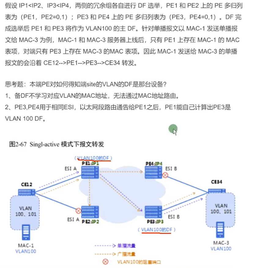
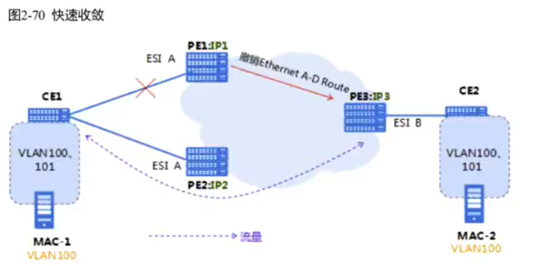
@以太自动发现路由(Ethernet Auto-Discovery Routa) : PE 之间的 BGP 邻居关系建立成功后,.PE 之间会传递以太自动发现路由。以太目动发现路由可以向其他 PE 通告本端 PE 对接入站点的 MAC 地址的可达性,主要用于 CE 多归属的场景中的水平分割和快速收敛。
以太网段路由 (Ethernet Segment Route) : 当 PE 之间的 BGP 邻居关系建立成功后,PE 之间会传递以太网段路由,用来实现连接到相同 CE 的 PE 设备之间互相自动发现。以太网段路由主要用于 CE 多归属场景中的 DF 的选举。在单归属场景中,主要涉及前两种路由的交互。接下来我们就看一下,这两种路由信息是如何促成控制面表项和隧道生成的。
type 1
双规场景下实现别名,快速收敛,水平分割
esi 用于实现 PE 是否连在一台 CE 上,本端 PE 知道,对端 PE 也知道
通过阻塞链路或者负载分担防环
阻塞链路:single active
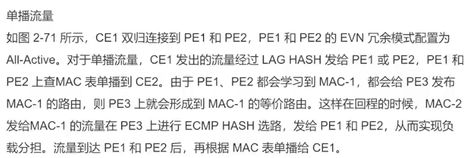
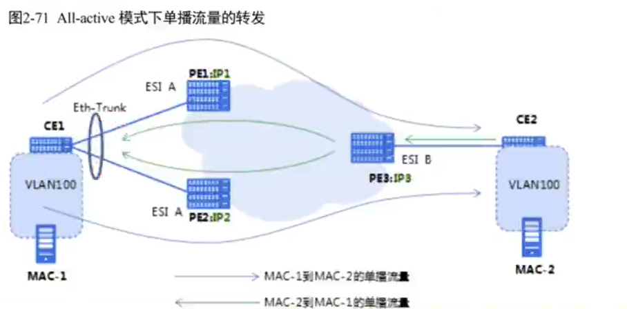
负载分担:all- active
多活时与 CE 相连的 PE 必须都是多活
有一个单活就必须使用第一种
1 2 3 4 5 6 7 8 9 10 11 12 13 14 15 16 17 18 19 20 21 22 23 24 25 26 27 28 29 30 31 32 33 34 35 36 37 38 39 40 41 42 43 44 45 46 47 48 49 50 51 52 53 54 55 56 57 58 59 60 61 62 63 64 65 66 67 68 69 70 71 72 73 74 75 76 77 78 79 80 81 82 83 84 85 86 87 88 89 90 91 92 93 94 95 96 97 98 99 100 101 102 103 104 105 106 107 108 109 110 111 112 113 114 115 116 117 118 119 120 121 122 123 124 125 126 127 128 129 130 131 132 133 134 135 136 137 138 vlan batch 30 100 200 vsys enable vsys name A 1 assign vlan 100 assign global-ip 203.1.1.1 203.1.1.10 free interface Vlanif100 ip binding vpn-instance A ip address 192.168.100.100 255.255.255.0 service-manage ping permit # interface Vlanif200 ip address 192.168.200.200 255.255.255.0 service-manage ping permit # interface GigabitEthernet0/0/0 undo shutdown ip binding vpn-instance default ip address 192.168.0.1 255.255.255.0 alias GE0/METH # interface GigabitEthernet1/0/0 undo shutdown # interface GigabitEthernet1/0/1 portswitch undo shutdown port link-type trunk port trunk allow-pass vlan 2 to 4094 # interface GigabitEthernet1/0/2 undo shutdown # interface GigabitEthernet1/0/3 undo shutdown # interface GigabitEthernet1/0/4 undo shutdown # interface GigabitEthernet1/0/5 undo shutdown # interface GigabitEthernet1/0/6 undo shutdown # interface Virtual-if0 # interface Virtual-if1 # interface NULL0 # firewall zone local set priority 100 # firewall zone trust set priority 85 add interface GigabitEthernet0/0/0 add interface Virtual-if0 # firewall zone untrust set priority 5 add interface Vlanif200 # firewall zone dmz set priority 50 # ip route-static 0.0.0.0 0.0.0.0 192.168.200.1 ip route-static 203.1.1.0 255.255.255.240 vpn-instance A # user-interface con 0 authentication-mode aaa idle-timeout 0 0 user-interface vty 0 4 authentication-mode aaa protocol inbound ssh user-interface vty 16 20 # switch vsys A sys interface Vlanif100 ip binding vpn-instance A ip address 192.168.100.100 255.255.255.0 service-manage ping permit firewall zone local set priority 100 # firewall zone trust set priority 85 add interface Vlanif100 # firewall zone untrust set priority 5 add interface Virtual-if1 # firewall zone dmz set priority 50 # location # nat address-group A 0 mode pat section 0 203.1.1.1 203.1.1.3 # multi-linkif mode proportion-of-weight # security-policy rule name test source-zone trust destination-zone untrust source-address 192.168.1.0 mask 255.255.255.0 source-address 192.168.2.0 mask 255.255.255.0 action permit # auth-policy # traffic-policy # policy-based-route # nat-policy rule name A source-zone trust destination-zone untrust source-address 192.168.1.0 mask 255.255.255.0 source-address 192.168.2.0 mask 255.255.255.0 action source-nat address-group A # quota-policy # pcp-policy # ip route-static 0.0.0.0 0.0.0.0 public ip route-static 192.168.1.0 255.255.255.0 192.168.100.1 ip route-static 192.168.2.0 255.255.255.0 192.168.100.1 # return